Preface#
I built a shared SPI driver that allows the nRF52840 to communicate with multiple devices on the same bus. Now that SPI communication is available, let’s put it to use by building a read-only SD card driver. This will allow the nRF52840 to read data blocks from an SD card, which I will eventually use to serve static websites through the web server.
GitHub Repo: https://github.com/codetit4n/nrf52840-webserver
Design Goals#
These are the design goals for the SD card driver in v1.0.0 of the project:
- Read-only operation: The SD card driver will be designed for read-only access, as the primary use case is to serve static files from the SD card.
- SDHC/SDXC support only: The driver will support only SDHC and SDXC cards, using block addressing. SDSC and older cards will not be supported.
- Shared SPI bus: The SD card driver will use the shared SPI bus implemented earlier, allowing it to coexist with other SPI devices, such as the W5500 Ethernet controller.
- Memory-efficient block reading: Read one 512-byte sector at a time, avoiding large data buffers and keeping memory usage low on the nRF52840.
Architecture#
The SD card driver sits between the application and the shared SPI driver, as illustrated in the diagram below. It handles SD card initialization, commands, responses, and block reads, while the shared SPI driver manages communication through the nRF52840’s SPIM0 peripheral.

SD Card SPI Protocol#
SD cards can communicate using either the native SD bus protocol or SPI. In this project, I am using SPI because it is simpler to implement and allows me to reuse the shared SPI driver built earlier. The SD card uses SPI mode 0 (CPOL = 0, CPHA = 0).
During initialization, the SPI clock is set to 250 kHz to ensure reliable communication with the SD card. Once initialization is complete, the clock frequency is increased to 2 MHz for faster data transfers. These frequencies are based on my hardware setup, and the card itself supports higher operating speeds.
Before sending any commands, the SD card needs at least 74 clock cycles with CS held HIGH and MOSI held HIGH. This allows the
card to complete its power-up sequence before entering SPI mode. The spi_clock_idle() function from the shared SPI driver
is used to generate these initial clock pulses.
Commands and Responses#
There are plenty of articles explaining SD commands and responses, and this is not a protocol tutorial, so I’ll focus only on what’s relevant to our implementation.
Communication with an SD card involves sending commands from the host and receiving responses from the card. In SPI mode, each command is 6 bytes (48 bits) long and contains a command index, a 32-bit argument, and a CRC7 field along with the start, transmission, and end bits. Commands are transmitted MSB first.
The following commands are used by the SD card driver:
| Command | Purpose |
|---|---|
| CMD0 | Reset the card and enter SPI mode |
| CMD8 | Check interface conditions and card compatibility |
| CMD55 | Indicate that the next command is an application-specific command |
| ACMD41 | Initialize the card and wait for it to become ready |
| CMD58 | Read the Operating Conditions Register (OCR) |
| CMD9 | Read the Card-Specific Data (CSD) register |
| CMD17 | Read a single 512-byte data block |
The response format depends on the command being sent. The driver handles three response types:
| Response | Size | Description |
|---|---|---|
| R1 | 1 byte | Card status and errors. 0x01 indicates idle, while 0x00 indicates no R1 error |
| R3 | 5 bytes | R1 followed by the 4-byte OCR, returned by CMD58 |
| R7 | 5 bytes | R1 followed by 4 bytes containing interface-condition information, returned by CMD8 |
The host must provide clock pulses to receive responses from the SD card. While waiting for a response, it transmits
dummy bytes (0xFF) until the card returns a valid response or a timeout occurs.
SD commands also contain a CRC7 field for error detection. In SPI mode, command CRC checking is disabled by default, so the driver uses valid CRC values for CMD0 and CMD8 and dummy CRC bytes for the remaining commands.
Data Transfers#
The driver reads one block at a time, following this sequence:
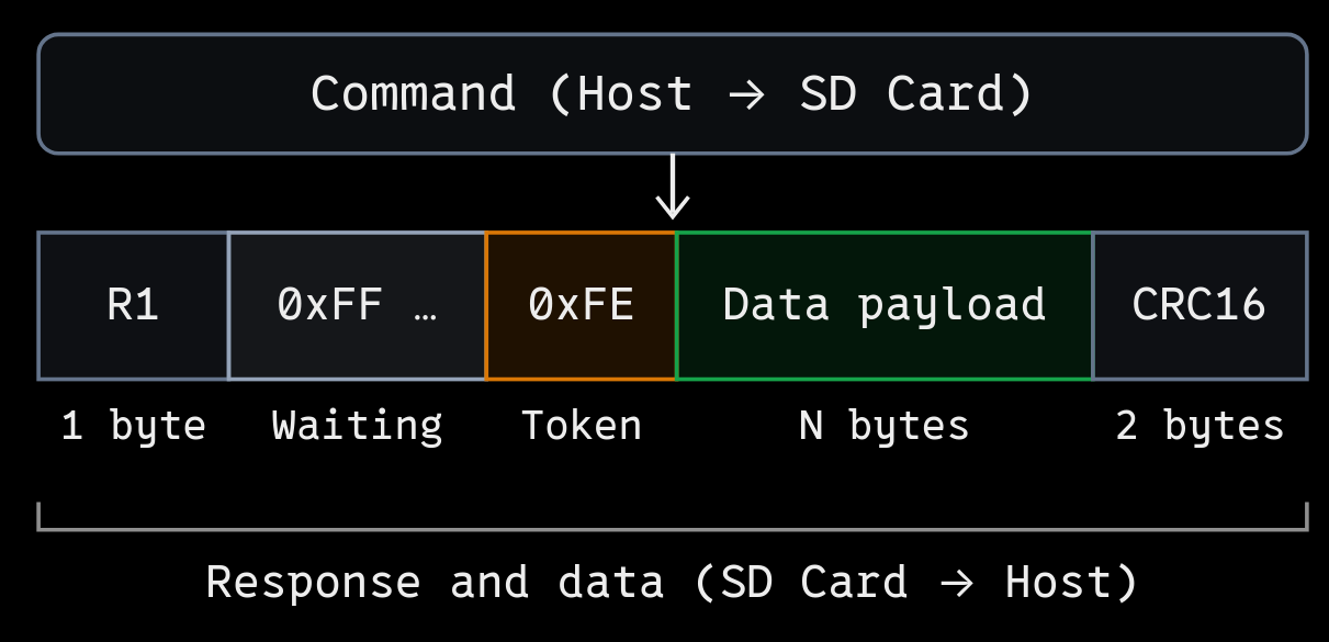
Once the host sends a read command and receives a successful R1 response (0x00), it continues transmitting dummy bytes
(0xFF) until the card is ready to send the requested data. The card sends a data token (0xFE) to indicate the start
of the data payload.
The size of the payload depends on the command being executed. For example, CMD9 returns 16 bytes of CSD data, while CMD17 returns a 512-byte block of data. The payload is followed by a 16-bit CRC used for error detection. In the current implementation, these two CRC bytes are read but not validated.
CS is held LOW throughout this entire sequence and is deasserted once the transfer is complete, allowing other devices to use the shared SPI bus.
SD Card Driver#
Relevant Source Code#
- Board Config Header - include/board.h
- Driver Header - include/drivers/sd.h
- Driver Source - src/drivers/sd.c
Command and Response Helpers#
Since sending commands and waiting for responses are common operations throughout the SD card driver, I implemented a few helper functions to avoid repeating the same logic for every command.
| Function | Description |
|---|---|
sd_begin_cmd() | Starts an SPI transaction, sends the command and waits for the R1 response, keeping the transaction open on success. |
sd_exec_cmd() | Sends a command, reads the R1 response along with any additional response bytes, and ends the SPI transaction. |
sd_end_cmd() | Ends the SPI transaction and generates eight additional clock cycles with CS HIGH. |
sd_wait_token() | Waits for the expected data token within a specified timeout. |
The reason for having two separate functions for sending commands (sd_begin_cmd() and sd_exec_cmd()) is that some
commands return only a response (like CMD0, CMD8 and CMD58), while others return a response followed by a data packet
(like CMD9 and CMD17).
For commands that return only a response, sd_exec_cmd() handles the entire SPI transaction internally. However, when
reading data from the SD card, we need to keep CS LOW and retain ownership of the shared SPI bus even after receiving
the R1 response. This is where sd_begin_cmd() comes in. Once the response is received, we can use sd_wait_token()
to wait for the data token, read the payload and CRC bytes, and finally call sd_end_cmd() to end the transaction.
These helper functions also handle SPI errors and response timeouts. If sd_begin_cmd() fails, it closes any SPI
transaction it has opened. However, if sd_wait_token() fails, the caller is responsible for ending the transaction
using sd_end_cmd().
Initializing the SD Card#
To communicate with the SD card, I use the spi_device_t structure
defined in the shared SPI driver from the previous article. The device configuration
for the SD card is as follows:
static spi_device_t sd_dev = {
    .cs_pin = SD_CSN_PIN,
	.mode = SPI_MODE_0, // CPOL = 0, CPHA = 0
	.frequency = SPI_FREQ_250K, // Low frequency for initialization
	.order = SPI_MSB_FIRST,
	.dummy_byte = 0xFF // Dummy byte for clocking and reading responses
};
NOTE: The
SD_CSN_PINis defined in the board configuration header file and is set to the GPIO pin connected to the SD card’s CS pin.
The SD card is initialized by calling the sd_init() function,
which performs the following steps:
- Reset the state variables and set the SPI frequency to 250 kHz. Resetting the state variables will come in handy for SD card recovery later.
- Initialize the CS pin and generate at least 74 clock cycles with CS HIGH and MOSI HIGH to prepare the card for initialization.
- Send CMD0 to reset the card and enter SPI mode.
- Send CMD8 to check the card’s interface conditions and compatibility, and reject legacy cards.
- Send CMD55 followed by ACMD41 repeatedly until the card is ready to operate.
- Send CMD58 to read the Operating Conditions Register (OCR) and determine if the card is SDHC/SDXC. Reject SDSC cards.
- Send CMD9 to read the Card-Specific Data (CSD) register and calculate the card’s capacity and total block count.
- Increase the SPI clock frequency to 2 MHz for faster data transfers and mark the card as initialized.
NOTE: The SD card initialization sequence is based on the SD Physical Layer Simplified Specification, which is the official document from the SD Association.
Before sending CMD0, we need to generate clock pulses without selecting the SD card. The usual spi_begin() function
asserts the CS pin LOW, which is not what we want here. For this purpose, I implemented a separate spi_clock_idle() function
in the shared SPI driver, which I did not cover in the previous article.
int spi_clock_idle(const spi_device_t* dev, size_t nbytes) {
    // ... validate the device and transfer size

    // take the mutex to ensure exclusive access to the SPI bus
    BaseType_t ok = xSemaphoreTake(spi_bus_mutex, portMAX_DELAY);
    // ... check if the mutex is acquired and no other device is active

    pin_high(dev->cs_pin); // keep the CS pin deasserted

    // configure the SPIM peripheral for the device
    // ... configure SPIM_CONFIG_REG for the mode and bit order
    SPIM_FREQUENCY_REG = dev->frequency;
    SPIM_ORC_REG = dev->dummy_byte;

    // ... clear events

    // fill the TX staging buffer with dummy bytes
    for (size_t i = 0; i < nbytes; i++) {
        tx_staging_buf[i] = dev->dummy_byte;
    }

    // configure EasyDMA buffers
    SPIM_TXD_PTR_REG = (uintptr_t)tx_staging_buf;
    SPIM_TXD_MAXCNT_REG = nbytes;

    SPIM_RXD_PTR_REG = (uintptr_t)scratch_buf;
    SPIM_RXD_MAXCNT_REG = nbytes;

    // start the transfer to generate clock pulses
    SPIM_TASKS_START_REG = 1;

    // ... wait for the transfer to complete, handle timeouts and clear events

    pin_high(dev->cs_pin);

    // release the shared SPI bus
    xSemaphoreGive(spi_bus_mutex);
    return 0;
}
The function acquires the shared SPI bus mutex and generates clock pulses by transmitting dummy bytes (0xFF in the
case of the SD card) while keeping CS HIGH. Any data received during the transfer is discarded using scratch_buf.
Unlike spi_begin(), this function does not set active_dev since no device is selected.
The function handles the entire transfer internally, including timeout handling and releasing the mutex, so there is
no need to call spi_end() after it returns.
CMD0 - Resetting the Card#
After generating the initial clock pulses, CMD0 is sent with CS LOW to reset the SD card and put it into SPI mode.
An SD card initially supports communication through its native SD bus interface. To select SPI mode, the host must assert CS LOW while sending CMD0. Once the card accepts CMD0 in SPI mode, it remains in SPI mode until the next power cycle.
The command packet is defined as follows:
static const uint8_t SD_CMD0[] = {
    0x40,                   // Command byte (CMD0)
    0x00, 0x00, 0x00, 0x00, // 32-bit argument
    0x95                    // CRC7 and end bit
};
CMD0 does not require any argument, so all four argument bytes are set to 0x00. The last byte (0x95) contains the
CRC7 value and the end bit. A valid CRC is required for CMD0 because the card has not yet entered SPI mode, where
command CRC checking is disabled by default.
The command is sent using sd_exec_cmd():
uint8_t r1 = 0xFF;

sd_status_t status = sd_exec_cmd(SD_CMD0, &r1, NULL, 0);

if (status != SD_OK) {
    // ... log error and abort initialization
    return status;
}
The card is expected to return an R1 response of 0x01, indicating that it has entered the idle state. This means
the card has accepted the reset command but is not yet ready for normal data transfers.
The card will remain in the idle state until the initialization process is completed using the subsequent commands.
CMD8 - Checking Card Compatibility#
After entering SPI mode, CMD8 is sent to check whether the SD card supports the supplied operating voltage and the newer SD card protocol.
The command is sent with a 32-bit argument of 0x000001AA, which contains two important fields:
- VHS (Voltage Supplied): Bits 11–8 indicate the voltage range supplied by the host. Setting this field to
0x1indicates the 2.7V–3.6V range. - Check Pattern: Bits 7–0 contain an 8-bit test pattern chosen by the host. In this case, I use
0xAA.
The command packet is defined as follows:
static const uint8_t SD_CMD8[] = {
    0x48,                   // Command byte (CMD8)
    0x00, 0x00, 0x01, 0xAA, // 32-bit argument (VHS = 1, check pattern = 0xAA)
    0x87                    // CRC7 and end bit
};
The check pattern helps verify that the card received the command argument correctly. The card echoes the pattern
in its R7 response, so we expect 0xAA in the final byte. The pattern itself is not special; another 8-bit value
could also be used.
In this implementation, the expected response is:
R1:         0x01
R7 payload: 0x00 0x00 0x01 0xAA
The R1 response of 0x01 indicates that the card is still in the idle state. The remaining four bytes confirm
the voltage information and check pattern.
The driver executes CMD8 and validates the response as follows:
uint8_t r7[4] = {0};

status = sd_exec_cmd(SD_CMD8, &r1, r7, sizeof(r7));

// ... handle SPI errors and timeouts

if (r1 == 0x05) {
    return SD_ERR_UNSUPPORTED_CARD;
}

if (r1 != 0x01 ||
    r7[0] != 0x00 || r7[1] != 0x00 ||
    r7[2] != 0x01 || r7[3] != 0xAA) {
    return SD_ERR_CMD_RESPONSE;
}
If the R1 response is 0x05, the card is reporting both the idle-state and illegal-command bits. This generally
indicates a legacy card that does not support CMD8. Since these cards are outside the scope of this driver,
initialization is aborted.
The driver also checks that the R7 response matches the expected values. If the voltage information or check pattern differs, it returns an error rather than continuing with initialization.
CMD55 + ACMD41 - Initializing the Card#
After checking compatibility, the next step is to bring the SD card out of its idle state.
This is done using ACMD41, which is an application-specific command. Unlike regular commands, application-specific commands must be preceded by CMD55, which tells the card that the next command belongs to the application-specific command set.
The command packets are defined as follows:
static const uint8_t SD_CMD55[] = {
    0x77,                   // Command byte (CMD55)
    0x00, 0x00, 0x00, 0x00, // 32-bit argument
    0xFF                    // Dummy CRC and end bit
};

static const uint8_t SD_ACMD41[] = {
    0x69,                   // Command byte (ACMD41)
    0x40, 0x00, 0x00, 0x00, // 32-bit argument (HCS = 1)
    0xFF                    // Dummy CRC and end bit
};
The argument for ACMD41 is 0x40000000. Here, bit 30 is set to 1, which is the HCS (Host Capacity Support)
bit. Setting this bit tells the card that the host supports high-capacity SD cards (SDHC/SDXC).
However, setting HCS does not mean that the connected card is necessarily an SDHC or SDXC card. We still need to check its capacity status later using CMD58.
The card may take some time to complete its internal initialization after power-up. Therefore, sending ACMD41 once is not necessarily enough.
The CMD55 and ACMD41 sequence is repeated until ACMD41 returns an R1 response indicating that the card is ready:
0x01: The card is still in the idle state and initialization is not complete.0x00: The card has exited the idle state and is ready for further commands.- Any other response: The driver treats it as an unexpected command response.
The initialization loop is implemented as follows:
uint8_t initialized = 0;

for (uint32_t i = 0; i < 100; i++) {
    status = sd_exec_cmd(SD_CMD55, &r1, NULL, 0);
    // ... handle command errors

    status = sd_exec_cmd(SD_ACMD41, &r1, NULL, 0);
    // ... handle command errors

    if (r1 == 0x00) {
        initialized = 1;
        break;
    }

    if (r1 != 0x01) {
        return SD_ERR_CMD_RESPONSE;
    }

    vTaskDelay(pdMS_TO_TICKS(10));
}

if (!initialized) {
    return SD_ERR_TIMEOUT;
}
In my implementation, the sequence is limited to 100 attempts. If the card is still initializing, the FreeRTOS task waits for 10 ms before trying again. This prevents the driver from continuously polling the card without giving up CPU time.
If the card does not become ready within the allowed attempts, initialization fails with a timeout error.
CMD58 - Checking Card Capacity Status#
Once the card has completed initialization, CMD58 is used to read the OCR (Operating Conditions Register).
The OCR is a 32-bit register that contains information about the card’s operating conditions, including its supported voltage range and capacity status.
The command packet is defined as follows:
static const uint8_t SD_CMD58[] = {
    0x7A,                   // Command byte (CMD58)
    0x00, 0x00, 0x00, 0x00, // 32-bit argument
    0xFF                    // Dummy CRC and end bit
};
CMD58 returns an R3 response, consisting of the one-byte R1 status followed by the four-byte OCR.
Two important bits in the OCR are:
- Bit 31 (Power-Up Status): Indicates whether the card has completed its power-up initialization.
- Bit 30 (CCS - Card Capacity Status): Indicates whether the card uses high-capacity block addressing.
The driver checks R1 and CCS but does not explicitly check bit 31.
In the implementation, we check the R1 response and extract the CCS bit from the OCR:
uint8_t ocr[4] = {0};

status = sd_exec_cmd(SD_CMD58, &r1, ocr, sizeof(ocr));
// ... handle command errors

if (r1 != 0x00) {
    return SD_ERR_CMD_RESPONSE;
}

uint8_t ccs = (ocr[0] & 0x40) ? 1 : 0;

if (!ccs) {
    return SD_ERR_UNSUPPORTED_CARD;
}
Since the OCR is transmitted MSB first, bit 30 is located at bit 6 of the first received byte (ocr[0]).
The mask 0x40 corresponds to binary 01000000, allowing us to isolate that bit.
If CCS is 1, the card uses block addressing, as supported by SDHC/SDXC cards. If CCS is 0, it uses
byte addressing, as with SDSC cards.
For example, suppose we want to read logical sector 10, with each sector containing 512 bytes:
| Card type | CMD17 address argument |
|---|---|
| SDHC/SDXC | 10 |
| SDSC | 5120 (10 × 512) |
This difference is important because the SD driver passes the requested block number directly as the CMD17 argument. Supporting SDSC cards would require additional handling for byte addressing.
Since the driver is designed only for SDHC/SDXC cards, it rejects cards where CCS is 0 and returns
SD_ERR_UNSUPPORTED_CARD.
Reading Card Information#
Once the SD card has completed initialization and we have confirmed that it is an SDHC/SDXC card, the next step is to read its Card-Specific Data (CSD) register using CMD9.
The CSD is a 128-bit (16-byte) register containing information about the card, including its capacity and other operating characteristics. Since the driver only supports SDHC/SDXC cards, it assumes the CSD version 2.0 format to determine the total number of addressable 512-byte blocks, without separately checking the CSD structure version.
CMD9 is defined as follows:
static const uint8_t SD_CMD9[] = {
    0x49,                   // Command byte (CMD9)
    0x00, 0x00, 0x00, 0x00, // 32-bit argument (unused)
    0xFF                    // Dummy CRC and end bit
};
Unlike commands such as CMD8 and CMD58, CMD9 does not return the CSD register directly as additional response bytes. Instead, it follows the data-transfer sequence discussed earlier.
After receiving an R1 response of 0x00, the host waits for the 0xFE data token. The card then transmits 16
bytes containing the CSD register, followed by two CRC16 bytes.
The relevant part of the implementation looks like this:
status = sd_begin_cmd(SD_CMD9, &r1);
// ... handle command errors

if (r1 != 0x00) {
    sd_end_cmd();
    return SD_ERR_CMD_RESPONSE;
}

// Wait for the data token
status = sd_wait_token(0xFE, 100);

if (status != SD_OK) {
    sd_end_cmd();
    return status;
}

// Read the 16-byte CSD register
uint8_t csd[16];

if (spi_rx(csd, sizeof(csd)) != 0) {
    sd_end_cmd();
    return SD_ERR_SPI;
}

// Read and discard the two CRC bytes
uint8_t crc[2];

if (spi_rx(crc, sizeof(crc)) != 0) {
    sd_end_cmd();
    return SD_ERR_SPI;
}

sd_end_cmd();
We use sd_begin_cmd() instead of sd_exec_cmd() because the SPI transaction must remain open after receiving R1.
The driver then waits for the data token and reads the CSD and CRC bytes using spi_rx(), while keeping CS LOW.
The two CRC bytes are read but not validated in this version of the driver. Finally, sd_end_cmd() closes the SPI
transaction and releases the shared SPI bus.
Calculating Card Capacity
In the CSD version 2.0 format, the C_SIZE field occupies bits 69–48 of the 128-bit register. It is a 22-bit value
spread across three bytes of the received CSD data.
We extract it as follows:
uint32_t c_size =
    ((uint32_t)(csd[7] & 0x3F) << 16) |
    ((uint32_t)csd[8] << 8) |
    (uint32_t)csd[9];
Here, csd[7] & 0x3F extracts the lower six bits of byte 7, which form the upper six bits of C_SIZE. Bytes 8 and
9 contain the remaining 16 bits. The values are shifted and combined using bitwise OR to reconstruct the complete
22-bit field.
For CSD version 2.0, the total number of 512-byte blocks is calculated using:
Block Count = (C_SIZE + 1) × 1024
The implementation uses a 64-bit calculation:
block_count = ((uint64_t)c_size + 1ULL) * 1024ULL;The multiplication by 1024 comes from the capacity encoding defined for CSD version 2.0, where each increment of
C_SIZE + 1 represents 512 KiB, or 1024 blocks of 512 bytes.
NOTE: Using a 64-bit calculation ensures that the result can represent the block count of larger SDXC cards without overflowing a 32-bit integer.
With the total block count available, the driver can determine the card’s capacity and validate block addresses before attempting to read data.
Finally, the SPI frequency is increased from 250 kHz to 2 MHz, and the SD card is marked as initialized:
sd_dev.frequency = SPI_FREQ_2M; // Operating frequency
sd_initialized = 1;
Reading Data Blocks#
Now that the SD card is initialized and its capacity is known, we can start reading data using the sd_read_block() function.
The function takes a block number and a pointer to a buffer where the data will be stored. Since the driver supports only SDHC/SDXC cards, each block contains 512 bytes, and the block number can be passed directly as the address argument to CMD17.
Before sending the command, the driver checks that the buffer pointer is valid, the card has been initialized, and the requested block number is within the card’s capacity.
CMD17 - Reading a Single Block
CMD17 is used to read one 512-byte block from the SD card. Unlike CMD9, which uses a fixed command argument, CMD17 requires the address of the block we want to read.
The driver constructs the command packet as follows:
uint8_t cmd17[6] = {
    SD_CMD17[0],
    (uint8_t)(block >> 24),
    (uint8_t)(block >> 16),
    (uint8_t)(block >> 8),
    (uint8_t)block,
    SD_CMD17[5]
};
The 32-bit block address is split into four bytes and transmitted in big-endian order (most significant byte first). Building the argument byte by byte ensures the SD command uses the correct wire order, regardless of the processor’s native endianness.
For example, if we want to read block 0x00000123, the four argument bytes will be 00 00 01 23.
The read operation follows the same data-transfer sequence as CMD9, except that we read 512 bytes instead of 16.
uint8_t r1 = 0xFF;

sd_status_t status = sd_begin_cmd(cmd17, &r1);
// ... handle command errors

if (r1 != 0x00) {
    sd_end_cmd();
    return SD_ERR_CMD_RESPONSE;
}

// Wait for the start-of-data token
status = sd_wait_token(0xFE, 100);

if (status != SD_OK) {
    sd_end_cmd();
    return status;
}

// Read 512 bytes into the caller's buffer
if (spi_rx(buffer, SD_BLOCK_LEN) != 0) {
    sd_end_cmd();
    return SD_ERR_SPI;
}

// Read the two CRC16 bytes
uint8_t crc[2];

if (spi_rx(crc, sizeof(crc)) != 0) {
    sd_end_cmd();
    return SD_ERR_SPI;
}

sd_end_cmd();

return SD_OK;
The card first returns an R1 response of 0x00, indicating that the command was accepted without an R1 error. The
driver then waits for the 0xFE data token before receiving the 512-byte block using spi_rx().
The two CRC16 bytes following the data are also received, but their values are not validated in this version of the driver.
As with CMD9, sd_begin_cmd() keeps the SPI transaction open until the data and CRC bytes have been received. The
driver then calls sd_end_cmd() to deassert CS and release the shared SPI bus. The same cleanup is performed when
an error occurs after the transaction has started.
This completes the basic read-only SD card driver. It can initialize supported cards, determine their capacity, and read individual 512-byte blocks without needing a filesystem.
Using the SD Card Driver#
With the driver implemented, the application can interact with the SD card through the functions exposed in sd.h.
The two primary functions are:
sd_init()— Initializes the SD card and reads its capacity information.sd_read_block()— Reads a specified 512-byte block into the provided buffer.
The driver also exposes functions for checking the card’s initialization and availability states, retrieving its total block count, and managing recovery requests. These allow the application to monitor the card’s state and coordinate recovery when failures occur.
A simple example of using the two primary functions is shown below:
sd_status_t status = sd_init();

if (status != SD_OK) {
    // Handle initialization failure
} else {
    uint8_t buffer[SD_BLOCK_LEN];

    status = sd_read_block(0, buffer);

    if (status != SD_OK) {
        // Handle read failure
    }
}
Here, sd_read_block(0, buffer) requests the first block of the SD card and stores its contents in the 512-byte buffer.
In an actual FreeRTOS task, the task stack needs enough space for this buffer.
The driver handles the SD commands, SPI transactions, data transfers, and error reporting internally. The application only needs to provide a valid block number and a buffer large enough to hold the data.
At this stage, the driver provides raw block-level access rather than file-level access. It does not understand files or directories, which is where FatFs comes in (next article).
Limitations#
The current driver has a few limitations:
- Supports only SDHC/SDXC cards.
- Read-only, with single-block (512-byte) reads.
- Does not validate CRC16 for received data.
These limitations are acceptable for the current web server implementation.
With that, we have a basic read-only SD card driver that can initialize SDHC/SDXC cards, determine their capacity, and read individual 512-byte blocks over the shared SPI bus.